 Please check the links above for more information on the Braille Reader and Dynamic Tags.
Wednesday, March 3, 2010
Braille Devices and Dynamic Tags
Please check the links above for more information on the Braille Reader and Dynamic Tags.
Monday, March 1, 2010
Update on LoRA
What we want to focus on:
- Triggering a memo/note at the required place and time (using RFID)
- Displaying the daily schedule in a intuitive manner.(Hopefully we can make a device which does this later)
- If possible , implement an algorithm which learns the users routine and adapts.
- System to tag important items in our daily life.
- Extend this location awareness using celphone tower information to low end devices.
- Change the function of the device depending on where you are.
Saturday, February 27, 2010
RFID Reader (Interfacing with FTDI cable)
As promised in the previous post .....here is the funda on interfacing the RFID Reader ID-20 to an FTDI cable
Where to buy: Sparkfun
Price : 35 USD
Stated Red range : 20 cm
Misc: The pin spacing and layout is awkward, you need to get the breakout board from sparkfun if it is going to be breadboard friendly( or you could always make one), the pinout of the more popular ID 12 is exactly the same as the ID 20, the ID 20 has a bit longer range.It also has an inbuilt antenna just like the ID 12.
You can find the datasheet here
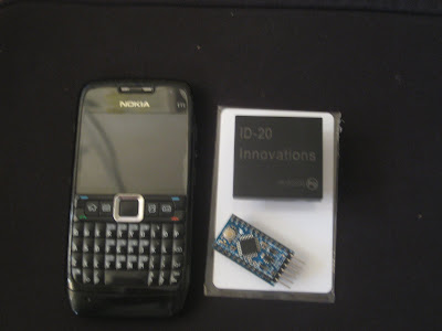
The Id-20, as you can see it is pretty big,this is because it has the antenna inside
This is how all the connections go, I wired it up for ASCII mode , there are several other modes which can be tried out, check the datasheet for them.
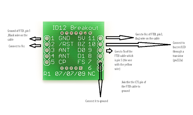
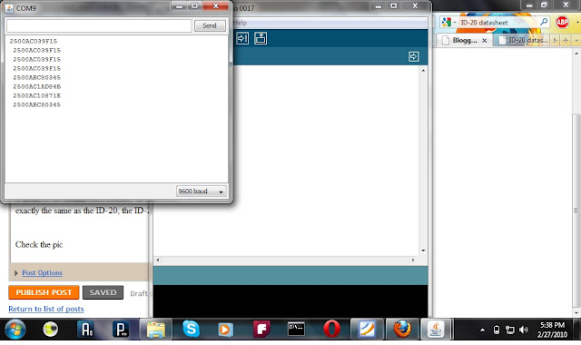
After all the wiring is done , just plug in the FTDI cable , select the right com port , set the baud rate to 9600, and voila you are reading RFID tags,just remember if you bring more than 2 tags into the read range there will not be any output , this is because both of them will be interfering with each other.
One more thing is that it will read a card only once so you need to take it away and then bring it close for it to read the card again and there is a minimum delay before it reads the same card again, though if it is a different card it is read almost instantaneously.
The protoboard made to house the ID 20 you can see the LED and the Beeper

The RFID Cards

The results on the Arduino serial terminal
Final Thoughts:
The range is around 13cm which is a bit less than the 16+ cm mentioned in the datasheet, but it may be different for different kinds of tags such as the button tags , glass capsules etc.
Also the read range varies with the orientation of the card , the best read range being for the face of the card parallel to the face of the IC (pretty obvious since the coil pattern on the card receives maximum flux when perpendicular to the field emitted by the IC)
That's it for now....I will post as soon as we get this working with an iPod Touch. i will also post an arduino shield for this IC
Where to buy: Sparkfun
Price : 35 USD
Stated Red range : 20 cm
Misc: The pin spacing and layout is awkward, you need to get the breakout board from sparkfun if it is going to be breadboard friendly( or you could always make one), the pinout of the more popular ID 12 is exactly the same as the ID 20, the ID 20 has a bit longer range.It also has an inbuilt antenna just like the ID 12.
You can find the datasheet here
The Id-20, as you can see it is pretty big,this is because it has the antenna inside

This is how all the connections go, I wired it up for ASCII mode , there are several other modes which can be tried out, check the datasheet for them.

After all the wiring is done , just plug in the FTDI cable , select the right com port , set the baud rate to 9600, and voila you are reading RFID tags,just remember if you bring more than 2 tags into the read range there will not be any output , this is because both of them will be interfering with each other.
One more thing is that it will read a card only once so you need to take it away and then bring it close for it to read the card again and there is a minimum delay before it reads the same card again, though if it is a different card it is read almost instantaneously.
The protoboard made to house the ID 20 you can see the LED and the Beeper

The RFID Cards

The results on the Arduino serial terminal

Final Thoughts:
The range is around 13cm which is a bit less than the 16+ cm mentioned in the datasheet, but it may be different for different kinds of tags such as the button tags , glass capsules etc.
Also the read range varies with the orientation of the card , the best read range being for the face of the card parallel to the face of the IC (pretty obvious since the coil pattern on the card receives maximum flux when perpendicular to the field emitted by the IC)
That's it for now....I will post as soon as we get this working with an iPod Touch. i will also post an arduino shield for this IC
Sunday, February 21, 2010
LoRA-Location based Reminding Aid
Location based reminding aid.............
Team:
Sujay
Varun(me)
Joy
Tejashree
This is our project for the HCI course in IDC......link to the course homepage
The challenge was to make a reminding aid to help people manage their lives better ....so after some brainstorming we cam to the conclusion that reminders should also be location based as they are time based(read alarms).
This is the gist of our implementation...more to come as we proceed
Parts used
Team:
Sujay
Varun(me)
Joy
Tejashree
This is our project for the HCI course in IDC......link to the course homepage
The challenge was to make a reminding aid to help people manage their lives better ....so after some brainstorming we cam to the conclusion that reminders should also be location based as they are time based(read alarms).
This is the gist of our implementation...more to come as we proceed
- The quick and dirty prototype we are making uses an RFID reader attached to a mobile device(read ipod touch)
- They identify the different areas at home (such as workspace,kitchen,closet etc)
- Then there is the to-do/organizer list the software then pulls up the relevant information from this list(extending this to integrate online services,outlook,goggle calendar,voice notes etc.)
- Example say you have a to do not saying that you need to buy more groceries so whenever you enter the kitchen or leave the house ...the device will show you that note....its simple.
- Few issues are there, like(it may be irritating to have a constant barrage of reminders etc )....we are working on sorting it out.
Parts used
- RFID reader-ID-20, bought it from Sparkfun
- RFID cards
- iPod Touch
Friday, February 19, 2010
Arduino Comparision
Just received my shipment from Sparkfun today,it had the Arduino pro mini along with an RFID reader(ID-20 ,more on that in my next post) and some RFID tags.....i decided to see the other alternatives to the pro mini , read on to find what i have come up with.
I have compared only the Arduino boards with the smallest footprints and surface mount chips........and I have only worked with the Arduino pro mini out of all that I mentioned....this list is not comprehensive and there may be other similar Arduino / arduino compatible boards. Just search for them on the arduino website or some online store. The information is only based on the latest v of these boards(as of the date of this post).
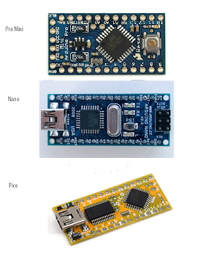
Here is a comparison Arduino Pro Mini (Sparkfun) vs Arduino Nano (Gravitech) vs Arduino Pico(Modified Electronics)
I have compared only the Arduino boards with the smallest footprints and surface mount chips........and I have only worked with the Arduino pro mini out of all that I mentioned....this list is not comprehensive and there may be other similar Arduino / arduino compatible boards. Just search for them on the arduino website or some online store. The information is only based on the latest v of these boards(as of the date of this post).
Here is a comparison Arduino Pro Mini (Sparkfun) vs Arduino Nano (Gravitech) vs Arduino Pico(Modified Electronics)

The images are NOT TO SCALE
Note: The on board regulators cannot source much current and you should not draw more than the specified voltage

*Without an on-board voltage regulator you have to supply the Vin pin with regulated 5V/3.3V through an external regulator or a adapter ,one more advantage of having an on board regulator is that you can power other devices with the same board. Also powering such boards with Li-polymer batteries is convenient as two of them give 7.4V and this will get well regulated to 5V
Note: The on board regulators cannot source much current and you should not draw more than the specified voltage
** The connectors to the pins on the boards,actually even if you know a bot of soldering boards without pin headers are preferable as it gives you the flexibility to solder the ones of your choice...which is very important if you are trying to make everything compact and small
Hope that helps you choose your arduino.................................................
Hope that helps you choose your arduino.................................................
Sunday, January 31, 2010
NOTE
Monday, November 23, 2009
Writing with solder
So recently(the last few months) I have become obsessed with the idea of conductive inks and making circuits on fabric and paper, I think it is sheer brilliance to be able to design and build circuits as seamlessly as drawing on a piece of paper, now there are several products which achieve this , such as conductive thread , conductive ink and writing instruments etc (search for bare conductive on google).The thing is that by designing tools and technologies which enable us to do so will allow us to deal more with these circuits , we feel it as art, and because it is so much more simpler and fun we will do it more often not to mention the infinite creative possibilities which it will open up. Such a wonderful thought it is.
So being inspired and all I was looking at ways it can be done, here is what I tried.
- First the simplest thing, you know pencil is made of graphite, and it is a good conductor of electricity, so I tried making marks of pencils on paper and measure the resistance. Obviously you need to make a very dark mark and greater the thickness greater is the conductivity. Typically with a mark of about 1cm long an 3 mm wide the resistance was about 400 k ohms and it was pretty much obeying ohms law( the longer the mark the greater the resistance)
- Next it struck me that if I make two patches of pencil marks on the either side of the paper it will for a capacitor I tried it out but did get the chance to test it ( exams and all right now ), but it should have it in the order of picofarads .
- Finally I decided to make an el cheapo version of a silver ink pen, to make it cheap, it does not have silver ink, instead as you write it leaves a solder wire on the paper( non melted), there are improvements to make like making the solder wire adhesive and making the tip a heating element do it can be fixed to any ic pin without any extra tools.
So this is what i made till now i converted a normal pen to dispense solder wire, i made a spindle on the top with the refill and an aluminum pipe, it does not look pretty but it all i had at 4 am in the night, i will post an instructable on this soon
This is how the solder path looks
I know this is very trivial, but it is sort of nice, ill post more when i improve itComing up resistor pen -set the value draw the resistorbye for now


Subscribe to:
Posts (Atom)